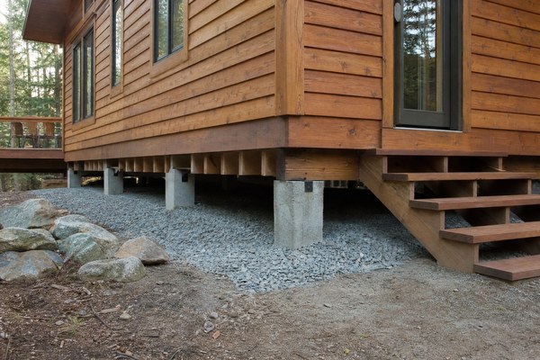
Determining the precise vertical clearance for a wooden cabin is one of the most critical preliminary engineering decisions in timber architecture and site preparation. For architects, developers, and project owners, establishing the correct elevation above finished grade directly influences structural longevity, moisture dynamics, thermal performance, and compliance with regional regulatory frameworks 1. While vernacular timber structures historically rested directly upon low stone footings or unreinforced timber pads, contemporary building standards demand a highly nuanced evaluation of soil mechanics, local frost lines, hydrological hazards, and subfloor ventilation requirements.
As a general guideline across typical light-frame and heavy-timber cabin installations, a finished floor elevation (FFE) sitting between 12 inches (305 mm) and 36 inches (914 mm) above adjacent grade represents the standard operating window. However, specific site conditions, flood plain mandates, and architectural typologies frequently necessitate variations ranging from ground-level monolithic slabs to elevated pile foundations exceeding several feet 2. This technical guide examines the multifaceted engineering parameters governing cabin elevation, providing architectural insights to optimize structural integrity, environmental resilience, and long-term asset value.
Direct Answer and Fundamental Clearance Benchmarks
In standard residential and recreational timber construction, establishing an adequate air gap between raw organic materials and the soil surface is imperative for structural preservation. Wood-destroying fungi, subterranean termites, and persistent moisture accumulation pose continuous threats to structural sill plates, floor joists, and rim boards. According to standard building science guidelines and international model codes, untreated wood framing members should maintain a minimum vertical separation of 6 inches to 8 inches from exposed earth, while wood siding and exterior wall finishes require even greater clearances—typically 6 inches from paved concrete surfaces and 8 inches from unprotected soil 3.
However, maintaining minimum code-prescribed clearances represents only the bare baseline for regulatory compliance. For prefabricated wooden cabins, modular timber chalets, and rural retreats exposed to severe weathering, a functional clearance of 18 to 24 inches is frequently recommended for crawlspace configurations. This elevated zone facilitates continuous cross-ventilation, accommodates plumbing supply lines, electrical conduit drops, and insulation blankets beneath the subfloor, and prevents snow accumulation or torrential splashback from dampening structural timber during severe weather events. For deeper insights into subgrade design, consult our guide on Choosing the Right Foundation for Your Prefab Wooden Cabin.
Geotechnical Conditions, Soil Bearing Capacity, and Frost Depth
The mechanical properties of the supporting soil substrate dictate both the foundation type and the resultant elevation of the cabin structure. Cohesive clay soils, granular sands, silts, and organic peat beds exhibit vastly different load-bearing capacities and settlement characteristics. Before finalizing cabin height, comprehensive geotechnical borehole testing or dynamic cone penetrometer testing is vital to determine allowable bearing pressure and soil shear strength 4.
Furthermore, frost heave represents a primary structural hazard in cold-climate regions. When moisture-laden soil freezes, it undergoes volumetric expansion, exerting immense upward pressure on shallow foundations and poorly elevated framing. To counteract frost heaving, structural footings must extend below the local frost line—a depth that varies significantly by geographic latitude and regional meteorology, ranging from a few inches in temperate zones to over 60 inches in subarctic environments. Consequently, piers or stem walls must bridge this frost-susceptible zone, lifting the cabin superstructure clear of shifting surface soils and ensuring load transfer to stable, unyielding subgrade strata 5.
Moisture Mitigation, Venting, and Timber Protection
Controlling moisture ingress is paramount when engineering wooden structures in natural landscapes. Ground moisture migrates upward through capillary action, hydrostatic pressure, and vapor transmission, creating a humid microclimate beneath unvented or low-clearance floors. Without adequate vertical separation and cross-ventilation, trapped humidity encourages fungal decay (such as brown rot, white rot, and soft rot) and attracts wood-boring insects, compromising the structural integrity of the timber chassis.
To mitigate these risks, elevated crawlspace designs must integrate continuous perimeter ventilation or mechanical vapor barriers. Building science standards generally specify a minimum net free ventilation area for crawlspaces—often calculated as 1 square foot of vent area for every 150 square feet of crawlspace floor area—combined with heavy-duty polyethylene ground cover acting as a vapor retarder to suppress soil moisture evaporation [6]. Elevating the cabin chassis higher above grade enhances natural convection currents beneath the floor assembly, lowering relative humidity and protecting structural floor joists, rim joists, and subflooring panels. For advanced strategies on safeguarding timber elements, review our manual on Moisture Control and Timber Preservation in Prefab Cabins.
Flood Plain Regulations, Grading, and Surface Drainage
Hydrological site analysis is equally influential in determining cabin elevation. Properties situated within designated 100-year or 500-year flood zones, coastal velocity zones, or high-precipitation watersheds are subject to strict statutory requirements. Local municipal planning authorities and environmental protection agencies enforce minimum elevation certificates, requiring the lowest horizontal structural member of a building to sit at or above the Base Flood Elevation (BFE) plus an additional freeboard margin (typically 1 to 3 feet depending on local municipal bylaws) [7].
Even on non-flood-prone sloped terrain, surface water management dictates building elevation. Finished grade must slope away from the cabin perimeter at a minimum gradient of 6 inches within the first 10 feet, as recommended by civil engineering best practices. If the natural topography funnels surface runoff toward the building footprint, raising the foundation via stem walls or timber piers prevents pooling against structural supports and directs drainage safely around the perimeter without causing soil erosion.
Structural Framing Systems: Piers, Piles, Crawlspaces, and Slabs
The chosen foundation typology imposes strict geometric limits on how high a wooden cabin can or should sit above ground. Each system possesses unique engineering trade-offs regarding cost, load distribution, site disturbance, and thermal performance:
- Concrete Piers and Post-and-Beam Systems: Ideal for sloped or ecologically sensitive sites, post-and-beam foundations utilize isolated concrete footings with timber or structural steel posts. This system allows variable elevation heights—from 12 inches to several feet—minimizing earth excavation and preserving natural root systems and existing surface drainage patterns.
- Continuous Stem Walls and Crawlspaces: Providing a robust perimeter enclosure, stem walls elevate the wooden floor system 18 to 36 inches above grade. They offer excellent wind uplift resistance, enhanced thermal mass, and secure, accessible space for mechanical utilities, though they require damp-proofing membranes, perimeter insulation, and engineered ventilation management.
- Helical Piles and Screw Piers: Rapid to install without major excavation, steel helical piles can elevate timber cabins across unstable soils, muskeg, or steep declivities. Height is easily adjusted via bolted connection brackets, making them favored for remote modular installations and low-impact building sites.
- Monolithic Slab-on-Grade: Placing the cabin directly on a reinforced concrete slab minimizes ground clearance (typically 4 to 8 inches above grade). While cost-effective on flat, stable, well-drained terrain, slabs eliminate under-floor access, complicate plumbing retrofits, and require meticulous edge insulation and thermal break detailing in cold climates.
Accessibility, Topography, and Architectural Integration
Beyond structural engineering and moisture control, human ergonomics and architectural proportion govern cabin elevation. Universal design principles and accessibility standards (such as the ADA or local equivalents) stipulate maximum threshold heights, maximum ramp slopes, and landing dimensions. A cabin sitting excessively high above ground requires extensive exterior staircases, expansive decking, or ADA-compliant ramps, which increase material costs, ongoing maintenance liabilities, and architectural complexity. Conversely, a cabin sitting too low relative to a sloping hillside may suffer from visual awkwardness, inadequate clearance for utility connections, and poor spatial connection with the surrounding landscape.
Architectural integration also involves balancing indoor-outdoor transitions. A moderate elevation of 18 to 24 inches aligns perfectly with standard porch deck heights, creating a welcoming threshold that connects interior living spaces with exterior terraces and viewing platforms. Careful topographical profiling ensures that the cabin sits harmoniously within its natural environment without appearing perched or severed from the earth. To ensure your site layout accommodates these structural elevations, consult our comprehensive Site Preparation Guide for Modular Wooden Structures.
Decision Framework: Selecting Your Optimal Cabin Elevation
Navigating the competing variables of soil mechanics, flood zoning, ventilation, and ergonomics requires a systematic engineering approach. Project owners must evaluate their specific site constraints against structural requirements to determine the optimal finished floor elevation.
| Site Condition / Constraint | Recommended Minimum Clearance | Primary Engineering Driver | Key Mitigation Strategy |
|---|---|---|---|
| Flat, Well-Drained Loam | 12 to 18 inches | Standard termite & moisture separation | Vapor barrier, crawlspace vents, treated sills |
| High Frost-Heave Risk | 24 to 36 inches (via piers) | Frost line depth & soil volumetric expansion | Deep concrete footings below frost line, isolated posts |
| Flood Zone / High Runoff | 24 to 48+ inches (above BFE) | Statutory flood compliance & surface water flow | Elevated pile/pier system, open foundation design |
| Sloped Hillside Terrain | Variable (12 to 60+ inches) | Topographical grade change & soil stability | Stepped post-and-beam piers, grade retention |
| Stable Bedrock / Flat Rock | 8 to 12 inches | Minimal soil moisture & shallow anchoring | Bolted steel pin anchors, low-profile sill framing |
This decision matrix illustrates that ground clearance is never a static architectural choice dictated solely by aesthetic preference. Rather, it is a calculated structural parameter derived from rigorous site evaluation, geotechnical testing, and statutory compliance.
Pre-Installation Engineering & Compliance Checklist
Before executing foundation excavation or ordering prefabricated timber framing components, project teams must complete a thorough pre-installation audit. Skipping regulatory or geotechnical validation can lead to catastrophic structural settlement, code violations, or premature moisture failure.
| Audit Phase | Action Item | Verification Standard / Focus Area | Responsible Party |
|---|---|---|---|
| 1. Geotechnical Audit | Subsurface soil testing & bearing analysis | Verify allowable soil bearing pressure and plasticity | Geotechnical Engineer |
| 2. Hydrological Survey | Flood plain mapping & surface drainage review | Confirm Base Flood Elevation (BFE) and local runoff paths | Civil Engineer / Surveyor |
| 3. Regulatory Review | Local municipal zoning & building code check | Ensure compliance with minimum height restrictions & frost depths | Project Architect / Permitting Lead |
| 4. Ventilation Planning | Subfloor cross-ventilation & vapor control | Calculate net free vent area and specify vapor retarders | Mechanical / Structural Engineer |
| 5. Material Specification | Timber durability & connector corrosion resistance | Verify pressure-treatment retention levels and fastener grades | Procurement & Engineering Team |
Following this structured checklist ensures that all environmental, structural, and statutory variables are accounted for prior to breaking ground.
Conclusion and Technical Scope Consultation
Determining how high a wooden cabin should sit above ground is a critical engineering decision that balances moisture protection, geotechnical stability, flood plain regulations, and architectural accessibility. While baseline timber preservation standards mandate a minimum separation of 6 to 8 inches from raw earth, real-world site conditions—such as deep frost lines, sloping topography, and statutory flood elevations—frequently dictate clearances ranging from 18 to 48 inches or more.
Because every building site presents unique soil mechanics, climatic exposures, and regulatory frameworks, applying a one-size-fits-all elevation is impossible. To ensure your upcoming wooden cabin project achieves optimal structural longevity, moisture resilience, and code alignment, we invite developers, architects, and private buyers to collaborate with our engineering specialists. Contact our team directly at info@owncabin.com to request a project-specific technical scope and foundation engineering assessment tailored to your site.