How Are Panelized Cabin Kits Assembled? A Step-by-Step Project Guide
Construction & Engineering
How Are Panelized Cabin Kits Assembled? A Step-by-Step Project Guide
Executive Summary & Direct Answer: Panelized cabin kits are assembled by erecting prefabricated wall, floor, and roof components—manufactured off-site under controlled factory conditions—onto a prepared foundation on-site. Unlike volumetric modular buildings or traditional stick-built construction, panelized systems arrive as flat-pack structural units, ranging from open panels (framing and sheathing) to closed panels complete with integrated insulation, service chases, and preliminary finishes. Assembly follows a rigorous engineering sequence: site preparation and foundation curing, crane- or manual-assisted placement of floor cassettes, sequential erection of exterior and interior load-bearing walls braced with temporary supports, installation of roof trusses or structural roof cassettes, and immediate weather-tight roof dry-in. Because structural definitions, building codes, occupancy classifications, and site installation rules vary significantly by jurisdiction, project stakeholders must consult the local Authority Having Jurisdiction (AHJ) and engage licensed local structural engineers and contractors prior to project execution 1.
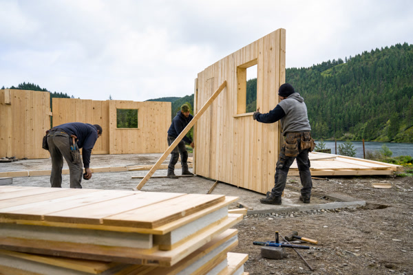
Crew assembling prefabricated timber wall panels on a cabin foundation
What Defines Panelized Timber Construction in Modern Cabin Projects?
In contemporary architectural design and boutique hospitality development, panelized timber construction occupies a strategic niche between volumetric modular building and traditional on-site stick-framing. A panelized cabin kit consists of prefabricated structural components—primarily exterior and interior wall panels, floor cassettes, and roof elements—engineered and fabricated in a precision-controlled manufacturing environment 3. Unlike modular cabins transported as fully enclosed three-dimensional boxes, panelized kits are transported flat-pack, making them exceptionally well-suited for remote, topographically challenging, or restricted-access rural sites where heavy transport trailers cannot navigate tight switchbacks, steep inclines, or narrow forest service roads.
The engineering premise underlying panelized construction is the transfer of labor-intensive framing operations from variable active job sites to stationary, climate-controlled plants. Raw timber materials, structural insulated panels (SIPs), or heavy mass timber posts are processed using computer-numerical-control (CNC) machinery to achieve precise dimensional tolerances. This manufacturing precision guarantees that framing members interlock with predictable exactness, minimizing on-site waste, structural settling, and weather-related timber degradation during the critical framing window. However, the degree of pre-finish and exact structural makeup vary widely depending on specific manufacturer engineering specifications and project-specific design choices.
From an architectural standpoint, panelized systems do not constrain aesthetic expression. Advanced timber cabin engineering allows project teams to execute sophisticated architectural geometries, expansive window openings, and complex roof pitches that would be exceedingly difficult or cost-prohibitive to erect using conventional stick-framing on remote terrain. Understanding the anatomy of these kits—distinguishing between open panels, which comprise framing and exterior sheathing only, and closed panels, which integrate factory-installed insulation, wiring conduits, interior linings, and exterior claddings—is the essential foundation of a successful project lifecycle 3. Furthermore, all construction methodologies must be evaluated against local environmental conditions, seismic zones, and regional snow or wind load requirements.
Parameter / Feature
Open Panel Systems
Closed Panel Systems
Volumetric Modular Prefab
Factory Completion Level
Framing and structural sheathing; services installed on-site.
Fully insulated, windows/doors, wiring chases, and interior/exterior finishes.
Completed off-site modules joined on-site; high factory enclosure.
Site Accessibility
High adaptability; fits on standard flatbed or light utility trailers.
Moderate to high; heavier panels require crane assistance and staging space.
Low to moderate; restricted by tight rural roads, bridges, and low overhangs.
On-Site Labor Requirement
Moderate skilled carpentry required for insulation, wiring, and finishes.
Minimal structural framing labor; primary focus on utility hookups and module mating.
Design Flexibility
High; easily modified or customized on-site during installation.
Moderate; requires strict adherence to factory engineering drawings.
Low; constrained by highway transport width and height regulations.
How Must Site Preparation and Foundation Engineering Be Handled Before Kit Delivery?
The physical assembly of a panelized cabin kit cannot commence without rigorous site preparation and precise foundation engineering. Because prefabricated panels are manufactured to strict dimensional tolerances—often within strict factory margins—any error, out-of-square condition, or unevenness in the foundation will cascade through the assembly process, resulting in misaligned wall studs, binding window frames, and compromised structural integrity. Therefore, comprehensive geotechnical investigations, topographical surveys, and soil-bearing capacity assessments must precede any manufacturing or shipping schedule.
Site preparation begins with clearing vegetation, topsoil stripping, and grading to ensure positive drainage away from the cabin footprint. Concurrently, the structural engineer and local civil designer must determine the optimal foundation type based on local climate, frost depth, soil mechanics, and seismic or wind exposure. Common foundation typologies for bespoke timber cabins include crawlspaces, engineered concrete slab-on-grade foundations, and elevated timber or steel pier foundations. For remote forested or mountainous sites, pier and beam or helical pile foundations are frequently preferred because they minimize site excavation and soil disturbance while accommodating sloping topography without massive earth-moving operations 2.
Once the foundation type is selected, anchor bolt placement, sill plate layout, and diagonal squareness measurements must be executed with extreme precision. Foundation contractors must install anchor bolts, hold-down brackets, and embedded steel leveling plates exactly where the structural engineering drawings specify. Prior to kit delivery, the foundation must undergo a formal curing and inspection sign-off by the local Authority Having Jurisdiction (AHJ) or a licensed local structural engineer to verify that all concrete compressive strengths and dimensional alignments satisfy governing building codes 1.
Foundation Type
Ideal Terrain / Climate
Structural Advantages
Key Assembly Considerations
Slab-on-Grade
Flat or gently sloping terrain; moderate frost depth zones.
Foundation stem wall top must be dead-level and square across all corners.
Pier & Beam / Helical Piles
Steep, rocky, or sensitive ecological sites; heavy snow loads.
Minimizes site excavation; prevents soil disturbance; allows airflow.
Structural moment connections and cross-bracing must be rigorously engineered.
What Are the Logistics, Unloading, and Material Staging Protocols on Remote Sites?
Coordinating the logistics, transportation, and on-site staging of a panelized cabin kit requires meticulous project management and advance planning. Unlike standard building materials delivered incrementally to an open urban job site, a panelized kit typically arrives in tightly coordinated transport convoys carrying entire floor cassettes, wall packages, roof trusses, and associated hardware crates. If any single component is damaged, misplaced, or staged incorrectly during offloading, the entire assembly sequence can experience costly delays.
Logistical planning must account for rural road weight limits, bridge load capacities, seasonal mud restrictions, and turning radii for long-bed tractor-trailers. In instances where remote alpine or forested parcels lack adequate road infrastructure, secondary transport solutions—such as all-terrain heavy-duty telehandlers, tracked crawlers, or localized crane transloading yards—must be established in cooperation with local transport authorities. Project managers should conduct a pre-delivery route survey several weeks prior to dispatch to identify overhead utility lines, low-hanging tree branches, narrow culverts, and bridge restrictions 3.
Upon arrival at the site, unloading and staging must follow a strict reverse-assembly protocol. Components needed last (such as interior partition panels and trim packages) are placed at the bottom of the stack or in secondary storage, while floor cassettes and first-sequence exterior wall panels are positioned immediately adjacent to the foundation footprint. Weather protection is paramount: panels must be elevated off damp ground using dunnage blocks and covered with breathable, UV-resistant waterproof tarpaulins to prevent moisture absorption, warping, or delamination of wood structural panels prior to erection. Proper staging ensures high site safety and efficient crane pick cycles.
How Are Floor Systems and Subfloor Cassettes Positioned and Anchored?
The physical erection sequence of a panelized cabin begins at the foundation interface with the installation of the floor system. Whether the design calls for traditional platform framing built on-site or prefabricated floor cassettes delivered from the factory, establishing a perfectly level, square, and structurally anchored floor platform is the single most critical milestone in ensuring vertical wall alignment and overall structural integrity.
The process commences with the placement of closed-cell sill gaskets over the concrete foundation stem wall or pier top plates to interrupt capillary moisture transfer and air infiltration. Pressure-treated sill plates are then laid over the gasket and secured using heavy-duty anchor nuts and oversized washers torqued to structural engineering specifications. Every corner is checked using diagonal tape measurements to confirm that the perimeter is perfectly square—meaning the diagonal measurements from corner to corner match within strict tolerances specified by engineering guidelines 5.
Once the perimeter framing is secured, floor joists or prefabricated floor cassettes are set into position. Floor cassettes—comprising rim joists, engineered I-joists or open-web wood trusses, and tongue-and-groove structural subfloor sheathing—are lifted via crane or telehandler directly onto the sill plates. Subfloor panels are fastened using a combination of structural construction adhesive and ring-shank nails or screws driven by pneumatic tools to prevent future floor squeaks and ensure rigid diaphragm action against lateral loads. Openings for plumbing drops and HVAC duct risers are pre-cut in the factory, requiring careful alignment with under-floor utility rough-ins before final fastening.
What Is the Sequence for Erecting Prefabricated Wall Panels and Structural Framing?
With the floor platform secured, swept clean, and chalk-lined with exact wall layout coordinates, the erection of the vertical wall panels begins. This phase is characterized by high mechanical efficiency, as prefabricated wall panels—complete with exterior sheathing, structural studs, window headers, and corner posts—are hoisted and locked into place in accordance with engineered shop drawings.
The erection sequence universally starts at a primary building corner, typically anchored by a pre-engineered corner post assembly. The first exterior wall panel is lifted by crane or crew, set onto a foam or mastic bedding seal along the subfloor chalk line, and plumbed vertically using spirit levels and magnetic plumb bobs. Once vertical alignment is achieved, temporary diagonal timber braces are anchored to the interior subfloor and screwed into the panel framing to hold it rigidly in place. Subsequent exterior wall panels are sequentially connected using face-nailing schedules, structural through-bolts, or proprietary interlocking hardware specified by the kit manufacturer 3.
As wall panels are erected around the perimeter, interior load-bearing partition panels are integrated into the layout. Tie-down straps, hold-down anchor rods, and continuous metal tension ties are bolted through the wall framing down to the foundation to provide certified resistance against seismic lateral loads and high-velocity wind uplift, subject to local engineering calculations. Throughout this process, project supervisors must continuously verify that wall headers remain level and that rough window and door openings maintain precise squareness to prevent operational binding when glazing units are later installed 1.
How Are Roof Trusses, Cassettes, and Dry-In Envelope Systems Installed?
Once the exterior and interior load-bearing walls are fully erected, braced, and capped with a double top plate that interlocks wall joints, the project transitions to the overhead structural system: roof framing and dry-in envelope completion. Depending on the architectural style of the bespoke cabin—ranging from traditional gable roofs to contemporary shed designs—the overhead system may utilize prefabricated timber roof trusses, structural insulated roof cassettes, or heavy timber rafter systems.
For panelized kits utilizing roof trusses, a crane hoists the bundles onto the top plates where erection crews distribute them at engineered spacing intervals (typically 16 or 24 inches on center). Each truss is secured using permanent metal hurricane ties or seismic clips nailed directly to the wall top plate in accordance with wind uplift requirements. Temporary lateral bracing is immediately installed between trusses to prevent buckling during the installation of roof sheathing. Alternatively, when insulated roof cassettes are specified, large-format structural panels spanning from exterior wall to ridge beam are dropped sequentially into place, providing immediate thermal insulation alongside structural support 3.
Achieving immediate dry-in status is the primary objective of this phase. Once the roof framing or cassettes are secured, exterior-grade roof sheathing (plywood or OSB) is fastened across the assembly. Crews immediately roll out and mechanically fasten high-performance synthetic roof underlayment or ice-and-water shield over the entire roof deck. This critical milestone seals the interior structure against unpredictable weather events, protecting exposed timber framing and allowing interior finishing trades to commence safely beneath a watertight overhead canopy.
What Are the Critical Weatherproofing, Vapor Barrier, and Envelope Sealing Protocols?
A panelized cabin kit is only as durable as the continuity of its building envelope. Because timber and engineered wood products are susceptible to moisture accumulation, fungal decay, and thermal degradation, rigorous weatherproofing, vapor control, and air-sealing protocols must be executed flawlessly during assembly. All moisture management strategies must be tailored to the specific regional climate zone, annual precipitation rates, and temperature differentials governing the building site.
Exterior wall panels are typically wrapped in a vapor-permeable, water-resistive barrier (WRB)—commonly referred to as house wrap—that sheds liquid bulk water while allowing trapped interior moisture vapor to escape outward. All vertical and horizontal seams of the WRB must be taped with specialized flashing tape, and window and door rough openings must be integrated with self-adhering flashing membranes installed in shingle fashion to guarantee gravity-defied drainage 5.
Air sealing is equally vital for structural energy performance and compliance with modern energy conservation codes (such as the International Energy Conservation Code [IECC] or U.S. Department of Energy Building America guidelines) 5. Expanding low-expansion foam sealants and continuous gaskets are applied at all panel-to-panel mating joints, foundation interfaces, and penetrations. Ensuring a continuous, uncompromised air barrier prevents conditioned indoor air from exfiltrating into wall cavities, where it could condense on cold structural members and foster mold growth or structural rot over time.
Install bottom-to-top with 6-inch horizontal overlaps; tape all seams.
Reverse lapping around window headers, trapping water inside wall cavity.
Air Sealer / Gasket
Stops uncontrolled air infiltration across structural joints.
Apply continuous mastic or foam gaskets before panel-to-panel mating.
Gaps left at corner intersections or foundation thermal bridges.
Vapor Control Layer
Regulates interior moisture diffusion based on regional climate zone.
Position smart vapor retarders on the warm side of insulation in cold climates.
Installing impermeable vapor barriers on both sides of wall, trapping moisture.
How Are Mechanical, Electrical, and Plumbing (MEP) Rough-Ins Integrated into Panelized Systems?
Integrating mechanical, electrical, and plumbing (MEP) services into a panelized cabin kit requires advanced coordination between architectural design, factory pre-manufacturing, and on-site mechanical contractors. Unlike conventional stick-built construction where electricians and plumbers drill through studs ad hoc on-site, panelized systems incorporate pre-engineered pathways and service chases designed directly into computer-aided manufacturing (CAM) software.
In closed-panel systems, electrical wiring conduits, junction box recesses, and plumbing chases are frequently embedded directly within wall panels during factory fabrication. Pull strings are often pre-threaded through flexible conduits, allowing on-site electricians to rapidly pull wiring without breaching structural studs. In open-panel or SIP kits, dedicated vertical wire chases are routed through core insulation channels, while horizontal wiring paths are accommodated via pre-bored holes in framing studs located at standardized heights 3.
Plumbing rough-ins require careful vertical alignment with under-floor chases and foundation stub-ups. Because major drain, waste, and vent (DWV) stacks cannot easily be retrofitted through solid structural floor cassettes or laminated wall panels after assembly, plumbing locations must be verified against shop drawings before foundation concrete is poured or floor cassettes are locked down. HVAC distribution—such as mini-split heat pump refrigerant lines or centralized ductwork—is planned through exterior wall penetrations or dropped ceiling soffits designed specifically to preserve the thermal envelope without compromising structural headers.
What Regulatory Frameworks, Inspections, and Permitting Considerations Govern Panelized Assemblies?
Navigating the regulatory landscape for panelized cabin kits requires understanding that off-site manufacturing does not exempt a project from local building codes, zoning bylaws, and environmental regulations. Local classification, structural design, zoning compliance, permit acquisition, site requirements, and installation rules vary significantly by jurisdiction; landowners and developers must consult directly with the local Authority Having Jurisdiction (AHJ) and engage licensed local professionals before procuring or erecting any kit 1.
Regulatory compliance is anchored by model building codes such as the International Residential Code (IRC) and the International Building Code (IBC). In North America and international markets adopting model codes, panelized construction manufacturers must secure evaluation service reports—such as ICC-Evaluation Service (ICC-ES) reports—or third-party engineering certifications demonstrating that factory-produced panels meet or exceed structural load, fire resistance, and energy performance criteria mandated by regional codes 4. Additionally, off-site construction standards such as ICC/MBI 1200 provide standardized benchmarks for quality assurance in factory environments 1.
Permitting workflows typically involve a dual-track approval process:
1. Plan Review: The AHJ reviews architectural and structural engineering plans for the cabin kit alongside site-specific grading, septic, and foundation engineering plans.
2. Factory & In-Situ Inspections: Because factory assembly occurs off-site, many jurisdictions accept third-party independent inspection agency reports for structural framing, while local municipal inspectors conduct on-site inspections for foundation pouring, MEP rough-ins, and final occupancy certification 1.
Regulatory Phase
Key Responsible Party
Required Documentation / Deliverables
Compliance Standard / Code
Zoning & Land Use
Landowner / Local Civil Consultant
Site plan, setback verification, environmental impact study, septic permit.
Local Municipal Zoning Bylaws; Environmental Protection Acts.
Foundation inspection sign-offs, MEP rough-in test certificates, final occupancy audit.
Local AHJ building codes; National Electrical Code (NEC).
What Is the Decision Framework and Timeline for Landowners and Developers?
For international landowners, boutique hospitality developers, and private clients evaluating panelized timber cabin kits, project success hinges on structured project planning and realistic timeline management. Compared to traditional on-site stick-building—which is vulnerable to weather delays, labor shortages, and material damage on remote sites—panelized construction compresses the critical on-site structural erection window.
To evaluate whether a panelized kit aligns with project goals, stakeholders should apply a structured decision framework encompassing four core pillars:
1. Site Accessibility vs. Transport Limits: Assess whether the parcel can accommodate delivery trucks and crane staging. If access is severely constrained, evaluate whether panelized flat-pack kits offer superior feasibility over volumetric modular boxes.
2. Regulatory & AHJ Alignment: Engage local planning departments early to determine off-site construction acceptance policies, snow and wind load requirements, and third-party inspection recognition.
3. Budgetary & Labor Certainty: Contrast the factory production costs of panelized kits against volatile local labor availability. While kit procurement requires careful upfront capital planning, it can streamline on-site labor hours and reduce weather-related exposure risks.
4. Architectural Vision & Customization: Balance the standardization of pre-engineered panels with the desire for bespoke architectural finishes, ensuring that window placements, roof pitches, and interior layouts harmonize with the manufacturer’s engineering grid 3.
Project timelines vary according to manufacturing schedules, shipping logistics, and local permit processing speeds, requiring careful coordination among all project participants.
Key Buyer Questions to Ask Before Procuring a Cabin Kit
What level of pre-finishing is included in the base kit package? (Verify whether windows, exterior cladding, insulation, and interior paneling are factory-installed or field-installed).
Are stamped structural engineering calculations provided for our specific wind and snow load zone? (Ensure compliance with local AHJ requirements and site snow load standards).
What specialized equipment is required for on-site offloading and assembly? (Confirm whether a crane, telehandler, or specialized rigging crew must be contracted locally).
What warranty coverage applies to factory-fabricated structural components and building envelope seals?
Conclusion
Panelized cabin kit assembly represents a sophisticated synthesis of advanced timber engineering, precision factory manufacturing, and disciplined on-site execution. By shifting complex framing operations off-site, developers achieve superior structural quality and reduced weather-exposure risks on remote sites. However, successful project delivery remains linked to rigorous site preparation, strict adherence to local building codes, and close collaboration with the Authority Having Jurisdiction (AHJ) and licensed local professionals 1. Through meticulous planning and adherence to established off-site standards, panelized timber cabins deliver enduring architectural excellence.
Own Cabin Project Consultation
Own Cabin provides expert design advisory and engineering coordination services for bespoke timber cabins tailored to discerning landowners, architects, and boutique hospitality developers worldwide. Our advisory team collaborates closely with your local structural engineers, architects, and general contractors to ensure every panelized kit aligns with the structural demands and regulatory requirements of your specific site 3.
To discuss your upcoming cabin project, review engineering specifications, or request a customized architectural feasibility study, please contact our project advisory team directly at info@owncabin.com.